
Page 3 - Demo
P. 3
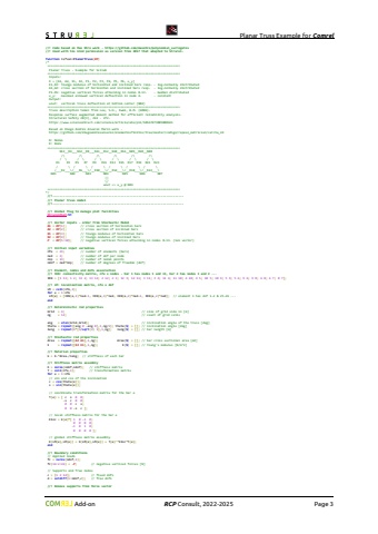
Planar Truss Example for Comrel Add-on RCP Consult, 2022-2026 Page 3//! Code based on Max Ehre work - https://github.com/maxehre/polynomial_surrogates//! Used with his kind permission as version from 2017 that adapted to Strurel.global StrurelPlotName StrurelPlotType StrurelPlotMode StrurelPlotCountfunction lsfval=PlanarTruss(XP)/*============================================================================ Planar Truss - Example for Scilab============================================================================ Inputs: X = [A1, A2, E1, E2, P1, P2, P3, P4, P5, P6, u_y] E1,E2: Youngs modulus of horizontal and inclined bars resp. - log-normally distributed A1,A2: cross section of horizontal and inclined bars resp. - log-normally distributed P1-P6: negative vertical forces attacking in nodes 8-13. - Gumbel distributed u_y: maximal allowed vertical deflection in node 4. - constant Output: uout: vertical truss deflection at bottom center (N04)============================================================================ Truss description taken from Lee, S.H., Kwak, B.M. (2006). Response surface augmented moment method for efficient reliability analysis. Structural Safety 28(3), 261 - 272. https://www.sciencedirect.com/science/article/abs/pii/S0167473005000421 Based on Diego Andr%u00e9s Alvarez Mar%u00edn work - https://github.com/diegoandresalvarez/elementosfinitos/tree/master/codigo/repaso_matricial/cercha_2d N: Nodes R: Rods============================================================================ N13__R4___N12__R8___N11__R12__N10__R16__N09__R20__N08 /\\ /\\ /\\ /\\ /\\ /\\ / \\ / \\ / \\ / \\ / \\ / \\ R1 R3 R5 R7 R9 R11 R13 R15 R17 R19 R21 R23 / \\ / \\ / \\ / \\ / \\ / \\ /___R2___\\/___R6___\\/__R10___\\/__R14___\\/__R18___\\/__R22___\\ N01 N02 N03 N04 N05 N06 N07 ||\\/ uout => u_y @ N04============================================================================*///!---------------------------------------------------------------------------//! Planar truss model//!---------------------------------------------------------------------------//! Global variables to manage plot facilitiesStrurelPlot=%tglobal StrurelPlotName StrurelPlotType StrurelPlotMode StrurelPlotCountStrurelPlotName='PlanarTruss_'; StrurelPlotType='.png'; StrurelPlotMode=int32(3)//! Vector inputs - order from Stochastic ModelA1 = XP(1); // cross section of horizontal barsA2 = XP(2); // cross section of inclined barsE1 = XP(3); // Youngs modulus of horizontal barsE2 = XP(4); // Youngs modulus of inclined barsP = XP(5:10); // negative vertical forces attacking in nodes 8-13. (1x6 vector)//! Initial input variablesnfe = 23; // number of elements (bars)ned = 2; // number of dof per nodennp = 13; // number of nodal pointsndof = ned*nnp; // number of degrees of freedom (dof)//! Element, nodes and dofs association//! IEN: connectivity matrix, nfe x nodes - bar 1 has nodes 1 and 13, bar 2 has nodes 1 and 2 ...IEN = [1 13; 1 2; 13 2; 13 12; 2 12; 2 3; 12 3; 12 11; 3 11; 3 4; 11 4; 11 10; 4 10; 4 5; 10 5; 10 9; 5 9; 5 6; 9 6; 9 8; 6 8; 6 7; 8 7];//! LM: localization matrix, nfe x dof LM = cell(nfe,1);for e = 1:nfe LM{e} = [IEN(e,1)*ned-1, IEN(e,1)*ned, IEN(e,2)*ned-1, IEN(e,2)*ned]; // element 1 has dof 1-2 & 25-26 ...end//! Deterministic rod propertiesGrid = 4; // size of grid side in [m]ng = 12; // count of grid cellsang = atan(Grid,Grid); // inclination angle of the truss [deg]theta = repmat([ang 0 -ang 0],1,ng/2); theta($) = []; // inclination angle [deg]leng = repmat(4*[1/sqrt(2) 1],1,ng); leng($) = []; // bar length [m]//! Stochastic rod propertiesArea = repmat([A2 A1],1,ng); Area($) = []; // bar cross sectional area [m2]E = repmat([E2 E1],1,ng); E($) = []; // Young's modulus [N/m^2]//! Material propertiesk = E.*Area./leng; // stiffness of each bar//! Stiffness matrix assemblyK = zeros(ndof,ndof); // stiffness matrixT = cell(nfe,1); // transformation matrixfor e = 1:nfe // sin and cos of the inclination c = cos(theta(e)); s = sin(theta(e)); // coordinate transformation matrix for the bar e T{e} = [ c s 0 0; -s c 0 0; 0 0 c s; 0 0 -s c ]; // local stiffness matrix for the bar e Kloc = k(e)*[ 1 0 -1 0; 0 0 0 0; -1 0 1 0; 0 0 0 0 ]; // global stiffness matrix assembly K(LM{e},LM{e}) = K(LM{e},LM{e}) + T{e}'*Kloc*T{e};end//! Boundary conditions// Applied loadsfc = zeros(ndof,1);fc(16:2:26) = -P; // negative vertical forces [N]// Supports and free nodesc = [1 2 14]; // fixed dofs
